Demo 1: Geometry
The code (tutorial/demo1-geometry.cpp) demonstrates the basic usage of the SlenderElemList class, covering construction, file I/O, accessing surface geometry, and visualization.
The SlenderElemList class is designed to represent slender-body geometries and use them in boundary integral equation (BIE) methods.
For the full API documentation please refer to slender_element.hpp.
Construction of Slender-Body Geometry
To construct a slender-body geometry, follow these steps:
We partition the geometry along its centerline into panels (slender-elements). For each panel, we choose the discretization order (
ElemOrder) along the centerline and the number of Fourier modes (FourierOrder).const Long Npanel = 8; Vector<Long> ElemOrderVec(Npanel), FourierOrderVec(Npanel); ElemOrderVec = 10; // Element orders along the length FourierOrder = 12; // Element orders in theta
The reference discretization in the [0,1] interval nodes for a panel of order
ElemOrderare given byCenterlineNodes(ElemOrder). For each panel, we determine the centerline coordinates (Xc) and cross-sectional radius (eps) at each discretization node along the centerline. In the following example code, we buildXc, andepsfor a circular loop:Vector<double> Xc, eps; for (Long i = 0; i < Npanel; i++) { // discretization nodes in [0,1] interval const Vector<double>& nodes = SlenderElemList<double>::CenterlineNodes(ElemOrderVec[i]); for (Long j = 0; j < ElemOrderVec[i]; j++) { const double phi = 2*const_pi<double>() * (i + nodes[j]) / Npanel; // circle parameterization phi in [0,2pi] Xc.PushBack(cos(phi)); // X-coord Xc.PushBack(sin(phi)); // Y-coord Xc.PushBack(0.0); // Z-coord eps.PushBack(0.1); // cross-sectional radius } }
Initialize the
SlenderElemListobject usingElemOrderVec,FourierOrderVec,Xc, andeps:SlenderElemList<double> elem_lst(ElemOrderVec, FourierOrderVec, Xc, eps);
File I/O
The SlenderElemList class provides methods to read from and write to files in a human-readable format. To perform file I/O:
Write the geometry data to a file:
elem_lst.Write("path/to/file.geom", comm);
Read geometry data from a file:
elem_lst.Read<double>("path/to/file.geom", comm);
The geometry file contains the coordinates, the cross-sectional radius, and the orientation vector at the centerline nodes of each panel along the centerline. An example of a geometry file is shown below:
#          X           Y           Z           r    orient-x    orient-y    orient-z   ElemOrder FourierOrder
  1.2812e-01  1.5108e-04  0.0000e+00  1.2500e-01  0.0000e+00  0.0000e+00  1.0000e+00          10           88
  1.2812e-01  1.3375e-03  0.0000e+00  1.2500e-01  0.0000e+00  0.0000e+00  1.0000e+00
  1.2812e-01  3.5943e-03  0.0000e+00  1.2500e-01  0.0000e+00  0.0000e+00  1.0000e+00
  1.2811e-01  6.7005e-03  0.0000e+00  1.2500e-01  0.0000e+00  0.0000e+00  1.0000e+00
  1.2809e-01  1.0352e-02  0.0000e+00  1.2500e-01  0.0000e+00  0.0000e+00  1.0000e+00
  1.2807e-01  1.4191e-02  0.0000e+00  1.2500e-01  0.0000e+00  0.0000e+00  1.0000e+00
  1.2804e-01  1.7842e-02  0.0000e+00  1.2500e-01  0.0000e+00  0.0000e+00  1.0000e+00
  1.2801e-01  2.0948e-02  0.0000e+00  1.2500e-01  0.0000e+00  0.0000e+00  1.0000e+00
  1.2799e-01  2.3205e-02  0.0000e+00  1.2500e-01  0.0000e+00  0.0000e+00  1.0000e+00
  1.2797e-01  2.4392e-02  0.0000e+00  1.2500e-01  0.0000e+00  0.0000e+00  1.0000e+00
  1.2797e-01  2.4694e-02  0.0000e+00  1.2500e-01  0.0000e+00  0.0000e+00  1.0000e+00          10           88
  1.2795e-01  2.5880e-02  0.0000e+00  1.2500e-01  0.0000e+00  0.0000e+00  1.0000e+00
  1.2792e-01  2.8137e-02  0.0000e+00  1.2500e-01  0.0000e+00  0.0000e+00  1.0000e+00
  1.2788e-01  3.1242e-02  0.0000e+00  1.2500e-01  0.0000e+00  0.0000e+00  1.0000e+00
  ....
Accessing Surface Geometry
You can retrieve the surface discretization nodes and normals using the GetNodeCoord method:
Vector<double> X, Xn;
Vector<Long> element_wise_node_cnt;
elem_lst.GetNodeCoord(&X, &Xn, &element_wise_node_cnt);
Visualization
Finally, you can visualize the geometry and surface normals using VTK. Write VTK visualization files using the WriteVTK method:
elem_lst.WriteVTK("path/to/output", Xn, comm); // visualize the surface normals
The resulting output file can be opened in ParaView:
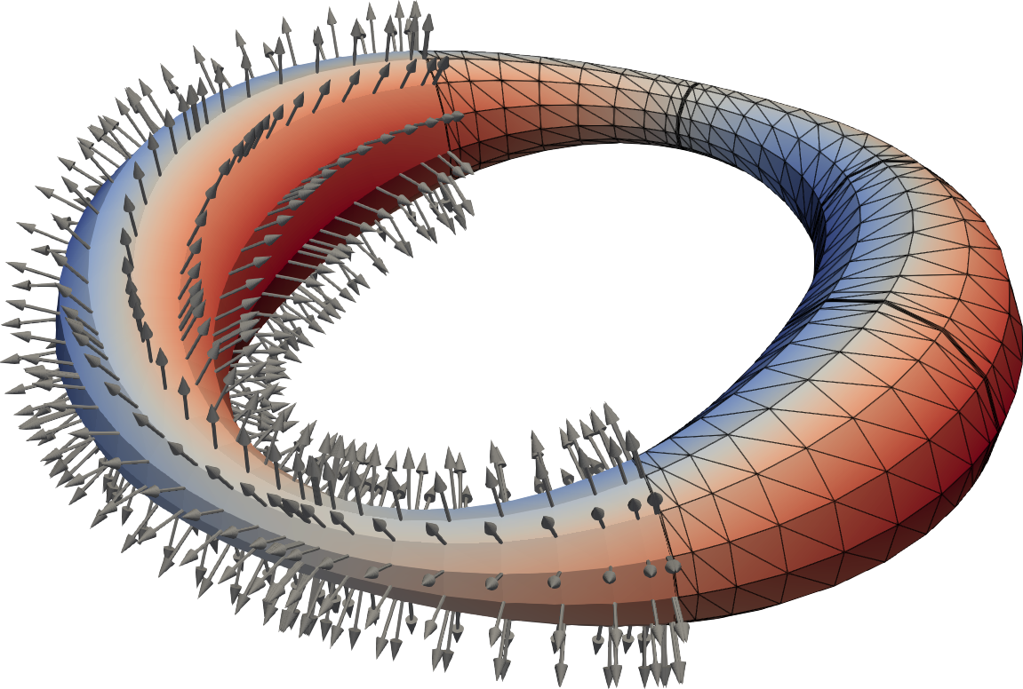
A circular ring with varying cross-section visualized in ParaView. The surface normal vectors are shown.
Compiling and Running the Code
To compile and run the provided code, navigate to the project root directory and run:
make bin/demo1-geometry && ./bin/demo1-geometry
This will generate the geometry file data/ring.geom and the VTK visualization vis/ring.pvtu which can be opened in ParaView.
Complete Example Code
/**
 * This demo code shows how to use the class sctl::SlenderElementList. The
 * class is declared in SCTL/include/sctl/slender_element.hpp. In particular,
 * we show how to:
 *
 * 1) construct a slender-body geometry from the coordinates of the centerline
 * and cross-sectional radius at each point on the centerline.
 *
 * 2) read/write the geometry from/to files (human readable).
 *
 * 3) get the surface discretization nodes and normals.
 *
 * 4) write VTK visualization of the geometry.
 *
 * To compile and run the code, start in the project root directory and run:
 * make bin/demo1-geometry && ./bin/demo1-geometry
 */

#include <csbq.hpp>
using namespace sctl;

int main(int argc, char** argv) {
  Comm::MPI_Init(&argc, &argv);

  {
    const Comm comm = Comm::World();
    SCTL_ASSERT_MSG(comm.Size()==1, "\
        This demo is sequential. In a distributed memory implementation, each process\n\
        would build only it's local section of the geometry.");

    // Quadrature files have been precomputed for 10th order elements (in 's')
    // and Fourier order (in 'theta') in multiples of 4 up to 100.
    const Long ElemOrder = 10;
    const Long FourierOrder = 12;

    const Long Nelem = 8; // number of elements
    Vector<double> Xc, eps; // centerline coordinates, and cross-sectional radius
    Vector<Long> ElemOrderVec(Nelem), FourierOrderVec(Nelem); // order in 's' and 'theta' for each element
    for (Long i = 0; i < Nelem; i++) { // loop over panels (build the centerline for a circle)
      ElemOrderVec[i] = ElemOrder;
      FourierOrderVec[i] = FourierOrder;

      // discretization nodes within a element in [0,1] interval
      const Vector<double>& nodes = SlenderElemList<double>::CenterlineNodes(ElemOrderVec[i]);

      for (Long j = 0; j < ElemOrderVec[i]; j++) { // loop over panel nodes
        const double phi = 2 * M_PI * (i + nodes[j]) / Nelem; // circle parameterization phi in [0,2pi]
        Xc.PushBack(cos(phi)); // x-coordinate
        Xc.PushBack(sin(phi)); // y-coordinate
        Xc.PushBack(0       ); // z-coordinate
        eps.PushBack((cos(2 * phi) + 2) * 0.1); // cross-sectional radius
      }
    }

    // Initialize the element list
    SlenderElemList<double> elem_lst(ElemOrderVec, FourierOrderVec, Xc, eps);

    elem_lst.Write("vis/ring.geom", comm); // write geometry data to file
    elem_lst.Read<double>("vis/ring.geom", comm); // read geometry data from file

    Vector<double> X, Xn; // the surface discretization nodes and normals
    Vector<Long> element_wise_node_cnt; // number of nodes per element
    elem_lst.GetNodeCoord(&X, &Xn, &element_wise_node_cnt); // get the surface geometry

    // visualizing the geometry and surface normals
    elem_lst.WriteVTK("vis/ring", Xn, comm);
  }

  Comm::MPI_Finalize();
  return 0;
}